![]()
![]()
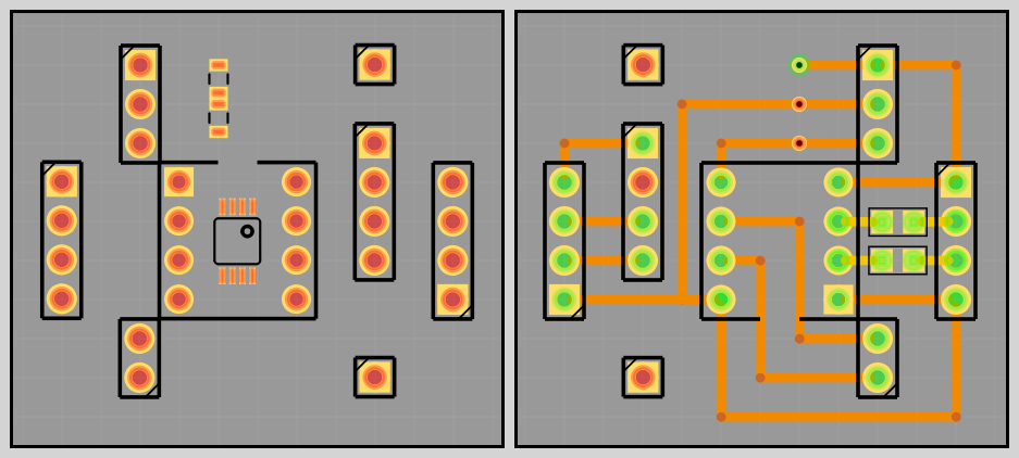
In the software "Fritzing" I made a connection diagram of the elements on the board.
You can download the source file of this scheme from my repository on GitHub
(link).
I will not go into all the subtleties of soldering, you can easily find a lot of video tutorials.
On my own behalf, I can recommend that you familiarize yourself with the course - PACE Worldwide Basic Soldering Lessons
(link).
This video tutorial series was created by PACE, Inc. back in the 1980s, but it remains as relevant as possible today,
since the laws of physics, the properties of solder, flux and heat transfer have not changed.
To solder all the elements on the breadboard, you need a conventional electric soldering iron and one of the types of flux (ordinary rosin is also suitable) to remove the oxide film during soldering, reduce surface tension and improve the spreading of liquid solder. It is not necessary to purchase an expensive soldering iron for this type of work, especially if you do not have them on a regular basis. The simplest so-called "blue soldering iron", which can probably be found in every hardware store, is enough.
This is a basic tool for soldering, with its advantages (in the form of cost) and its disadvantages (significantly overestimated the temperature set on the regulator and the final temperature on the tip itself, maintaining the temperature during operation is not entirely correct since the sensor is located at a great distance from the tip of the tip. But for basic work, it will be enough for you, but if you want to have a more convenient tool at hand for such work in the future, you can consider buying a digital soldering iron similar to the Miniware TS100 or a soldering station.
Since the middle of 2024, I have been using Alientek T80p on C245 type stingers in my arsenal.
Not so long ago, an updated version of the Alientek T90 was released, and the Sequre S99 model is also recommended on the forums.
But in this matter, the choice of device, as they say, is yours.
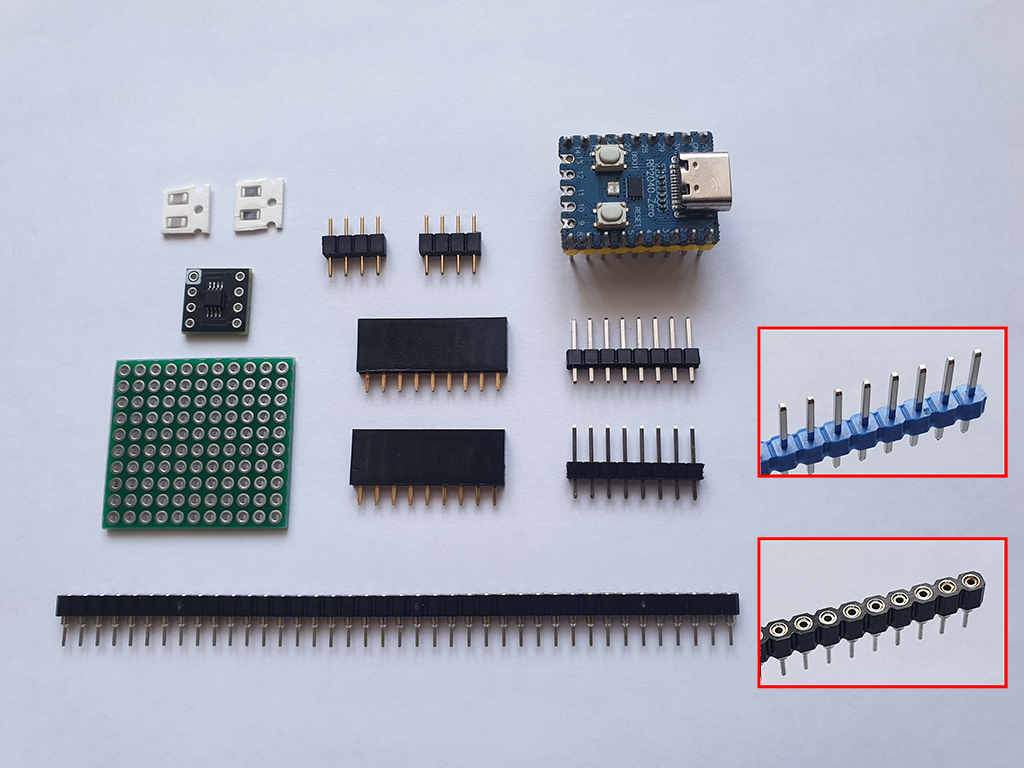
All the items are on our table and we are ready for further assembly.
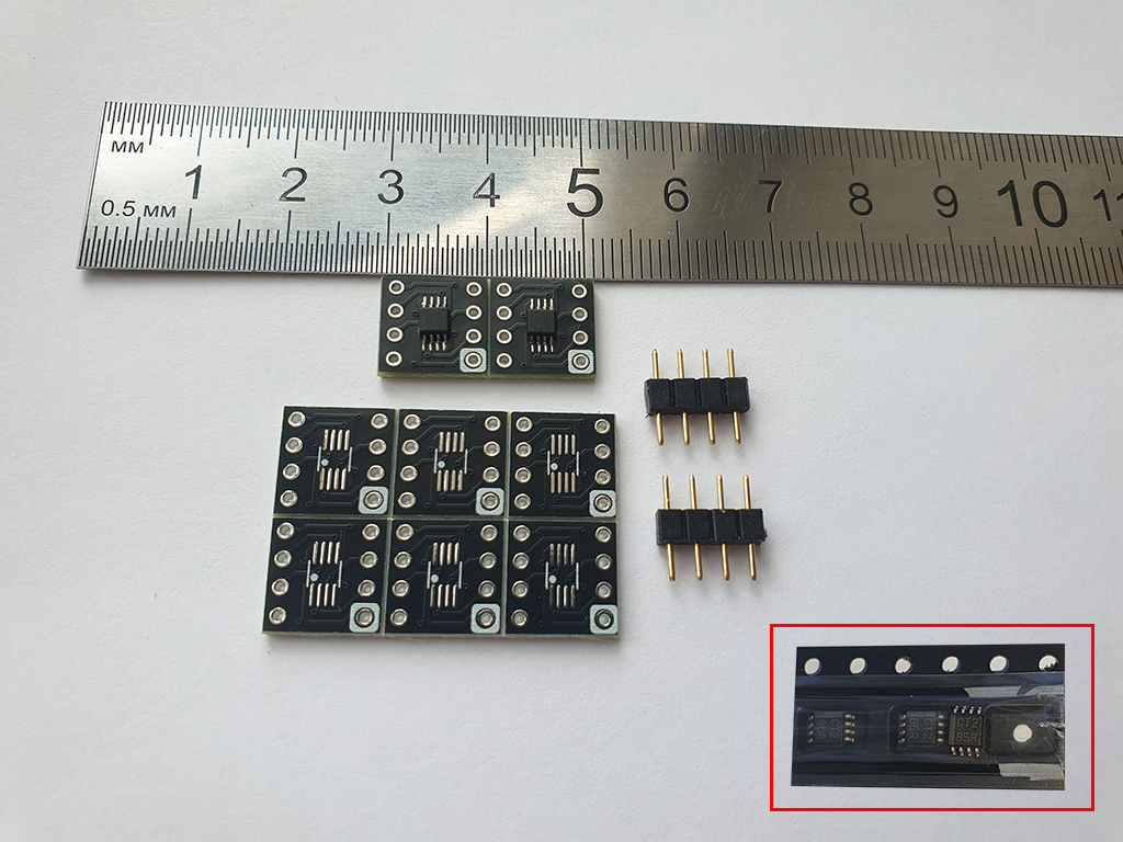
First, we need to solder the chip onto the adapter-board. The element is quite small, to work with it you need some experience with a soldering iron and a correspondingly thin tip (I use a 'BC2' type tip).
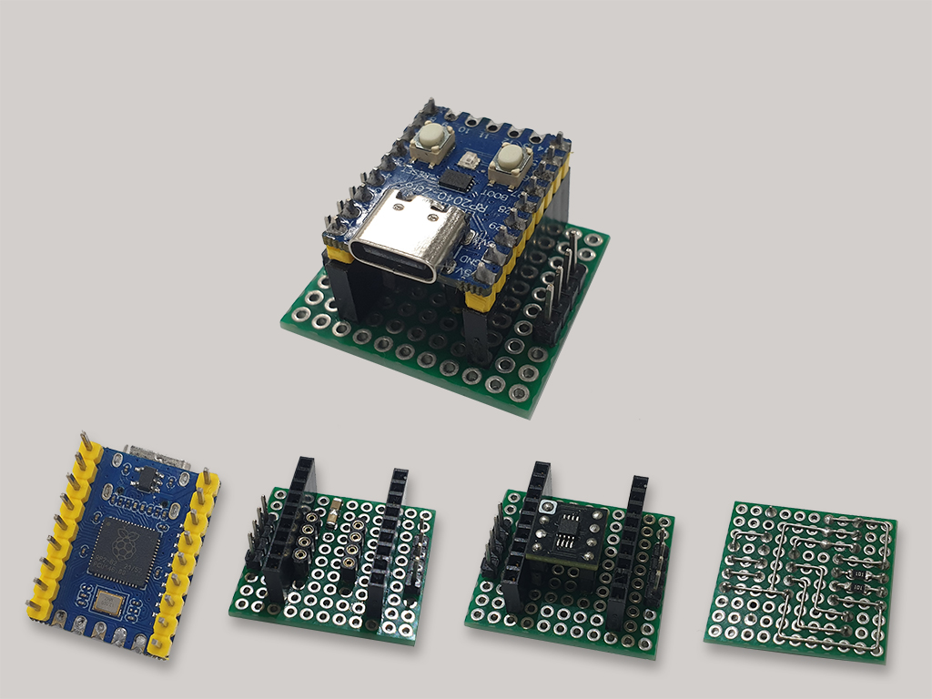
The result is such a compact printed circuit board with pre-prepared elements installed on it.

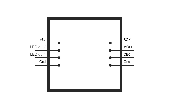
The block on the left side of the board is intended for two Data lines connected to the LED strip (in this version assembly uses parallel multi-segment mode) and +5v/Gnd connection from the power supply for power level switch and the Rp2040-Zero board itself. The block located on the right side of the board is intended for connection to Raspberry Pi (SPI bridge).
| Rp2040 | - | Raspberry |
|---|---|---|
| GPIO 2 | SCK | GPIO 11 |
| GPIO 4 | MOSI | GPIO 10 |
| GPIO 5 | CE0 | GPIO 8 |
| GND | GND | GND |
This completes this stage of preparing the LED driver.